Page 1 of 1
Jumper Settings J1 & J2

Posted:
Thu Feb 23, 2006 6:46 pmby mrosso
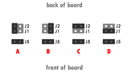
I'm a bit confused about which jumpers to short on the J99. I haven't been able to figure things out from the instructions or by searching this forum. What is the typical J1 & J2 setup for standard Large Dia Condenser mics? With "|" representing a jumper set vertically across pins and "__" representing a jumper set horizontally across pins, what is the correct setup?
| |
| |
or
__ __
__ __
or ?
Thanks,
Mar

Posted:
Sun Apr 23, 2006 7:13 pmby zonkola
I have the same question:
"Shorting across J1 and J2 with a
single jumper selects a 1:2.5 step-up ratio, and a 1000 ohm input impedance. Use this setting for most microphones."
I'm assuming this means A or B. (J5 is shown jumpered for context.) Which option is correct?


Posted:
Mon Apr 24, 2006 4:07 pmby tpryan
"A" is correct. You can verify by observing that PCB traces connect those pins to T1-2 and T1-4. Jumpering as in "B" connects CONN1-2 and CONN1-3 together, shorting the input signal. Jumpering as in "C" or "D" will work, but will result in higher distortion at a given input level than jumpering both J1 and J2.

Posted:
Thu May 10, 2007 12:08 pmby stickers
I am glad I found this post about the correct jumper setting at j1 and j2. It really should be illustrated clearly in the assembly instructions.
"shorting across j1 and j2" sure but which 2 sets of pins
Thanks zonkola and thanks tim for answering.

Posted:
Sat May 12, 2007 8:12 pmby Randyman...
I guessed. The first guess was wrong (like your "B"), and I got no signal

Swapped jumpers, and there we go!


Posted:
Wed Jul 04, 2007 10:29 amby Archmart
Hey Hey!
I'm glad for this thread. It really helped.
Now the obvious question, I think, is has anyone modified to add a switch here so we can switch the input impedance. I've got some ribbons and would appreciate the option.
I'm thinking a simple switch in drilled through the front panel that simply opens/closes instead of this jumper would do it.
I'm thinking the challenges would be...
A: avoiding a loud pop when switching and
B: introducing noise by running a wire all the way past all the other circuitry at such an early point in the circuit. (I suppose a switch on the back or well shielded wire would help this?)
But perhaps this is in another thread already?
Archmart

Posted:
Wed Jul 04, 2007 10:32 amby Archmart
Hey Hey!
Wait, no. The switch would have to open/close in three places... ?
Archmart

Posted:
Fri Nov 26, 2010 3:37 pmby Brian Ellingboe
so to set this up for a ribbon mic I would do two jumpers? like a combination of A and B?

Posted:
Fri Nov 26, 2010 4:45 pmby tpryan
Unless you have an ancient ribbon mic with a 30-50 ohm output impedance or absolutely must have another 6dB of gain, set the jumpers as shown in step 9 of the assembly instructions.

Posted:
Sun Nov 28, 2010 9:51 amby Brian Ellingboe
So if I want the added gain I jumper
across J1 and J2 like a combination of C and D..
Brian

Posted:
Tue Nov 30, 2010 1:43 pmby tpryan
So if I want the added gain I jumper across J1 and J2 like a combination of C and D.
Right.
