Purchased from someone else. Cannot get to pass signal.
Here are my voltages. Seems like I have a problem.
q1 3.9 2.5 1.5
q2 13.2 3.9 3.3
q3 22 13.2 12.6
q4 9.5 0.7 0.2
q5 21.4 9.4 8.9
q6 21.4 8.9 8.3
**adding info on card two***
q1 3.9 2.5 1.9
q2 13.1 3.9 3.3
q3 21.8 13.1 12.5
q4 9.0 0.8 0.2
q5 21.4 9.0 8.9
q6 21.4 8.4 87.8
I bought two, neither passed signal. Have not measured other yet.
Incorect voltages
16 posts
• Page 1 of 2 • 1, 2
Incorect voltages
![]() by jdier » Fri Sep 12, 2014 7:22 am
by jdier » Fri Sep 12, 2014 7:22 am
Last edited by jdier on Mon Sep 15, 2014 2:02 pm, edited 1 time in total.
- jdier
- Posts: 44
- Joined: Mon May 17, 2010 7:43 am
Re: Incorect voltages
![]() by Revson » Fri Sep 12, 2014 8:09 am
by Revson » Fri Sep 12, 2014 8:09 am
In for response as I was the seller. Both units tested as working prior to shipping and I'm trying to help figure out what's wrong.
The collector voltage is way high on Q4 (which connects directly to the base on Q5). Test the voltages on R35. One side of the resistor should be the same as the collector voltage and the other side should be 24Vdc. That line looks like it's connected to the input transformer's brown wire, if I'm reading the schematic right. The yellow line off that transformer should measure the same 21.4V as Q5 and Q6, although that appears to be a little low.
The collector voltage is way high on Q4 (which connects directly to the base on Q5). Test the voltages on R35. One side of the resistor should be the same as the collector voltage and the other side should be 24Vdc. That line looks like it's connected to the input transformer's brown wire, if I'm reading the schematic right. The yellow line off that transformer should measure the same 21.4V as Q5 and Q6, although that appears to be a little low.
- Revson
- Posts: 8
- Joined: Sun Feb 03, 2008 9:51 am
Re: Incorect voltages
![]() by Revson » Fri Sep 12, 2014 11:02 am
by Revson » Fri Sep 12, 2014 11:02 am
Actually, the brown and yellow wires are connected to the Output transformer (T2).
Can you test the voltage on both sides of D2? The side with the silver stripe side should be maybe around 29V and the other side should be 24V.
Can you test the voltage on both sides of D2? The side with the silver stripe side should be maybe around 29V and the other side should be 24V.
- Revson
- Posts: 8
- Joined: Sun Feb 03, 2008 9:51 am
Re: Incorect voltages
![]() by jdier » Fri Sep 12, 2014 1:11 pm
by jdier » Fri Sep 12, 2014 1:11 pm
Will check and report back next week.
Last edited by jdier on Thu Sep 18, 2014 6:09 am, edited 1 time in total.
- jdier
- Posts: 44
- Joined: Mon May 17, 2010 7:43 am
Re: Incorect voltages
![]() by jdier » Mon Sep 15, 2014 7:16 am
by jdier » Mon Sep 15, 2014 7:16 am
Second card measurements added to original post.
D2 measures 29.3 coming in, and 23.7 out, and on the other card 29.3/23.8
D2 measures 29.3 coming in, and 23.7 out, and on the other card 29.3/23.8
Last edited by jdier on Mon Sep 15, 2014 2:48 pm, edited 1 time in total.
- jdier
- Posts: 44
- Joined: Mon May 17, 2010 7:43 am
Re: Incorect voltages
![]() by tpryan » Mon Sep 15, 2014 7:58 am
by tpryan » Mon Sep 15, 2014 7:58 am
Can you adjust for 3.75V measured directly across R40? If R39 has no effect, re-flow the joints at Q4, Q5, Q6, and all the associated resistors, especially the 56K at R34.
- tpryan
- Site Admin
- Posts: 2078
- Joined: Thu Dec 04, 2003 11:32 pm
Re: Incorect voltages
![]() by jdier » Mon Sep 15, 2014 8:59 am
by jdier » Mon Sep 15, 2014 8:59 am
No problem adjusting down to 3.75 on either card.
reflowed joints regardless.
Same measurements
reflowed joints regardless.
Same measurements
- jdier
- Posts: 44
- Joined: Mon May 17, 2010 7:43 am
Re: Incorect voltages
![]() by Revson » Tue Sep 16, 2014 7:44 am
by Revson » Tue Sep 16, 2014 7:44 am
Can you measure continuity between the blue wire coming off T2 and either Pin 2 or 3 on the XLR output? Try doing the same with the violet wire.
- Revson
- Posts: 8
- Joined: Sun Feb 03, 2008 9:51 am
Re: Incorect voltages
![]() by tpryan » Tue Sep 16, 2014 9:02 am
by tpryan » Tue Sep 16, 2014 9:02 am
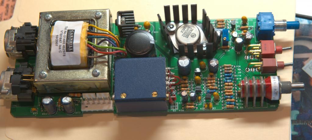
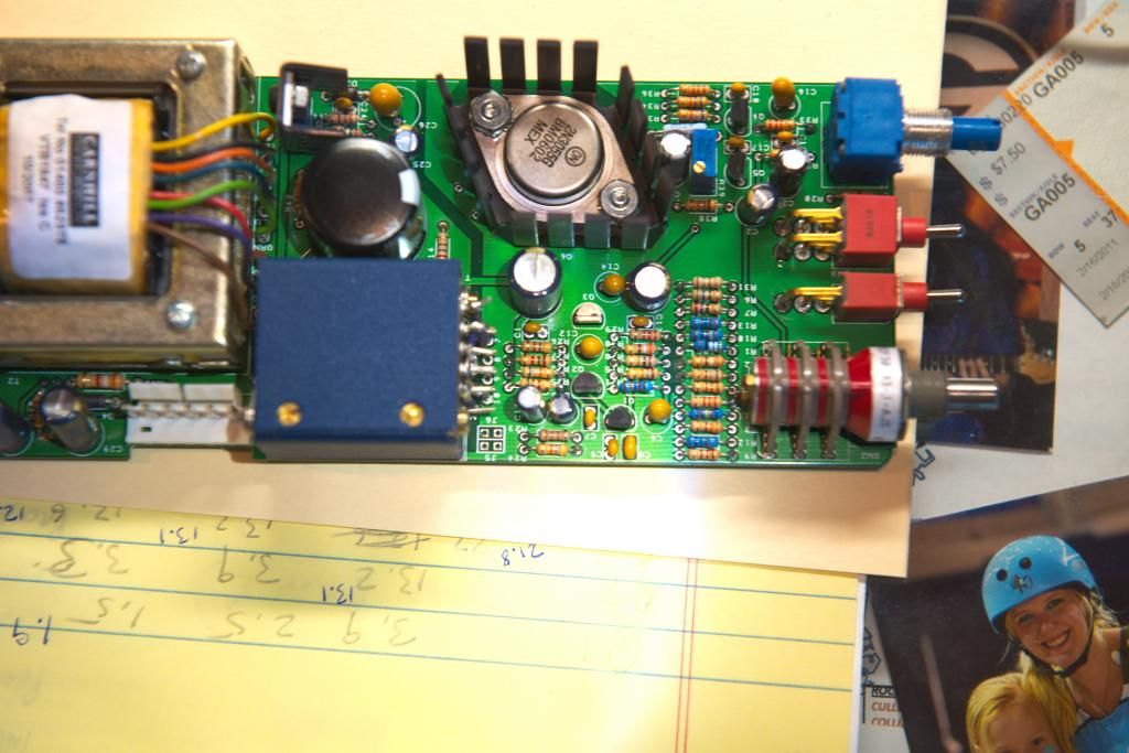
Can you post a photo of the input transformer wiring and jumpers? Also, a photo of the entire module?
PS: you will get much faster responses to specific questions if you email sales@seventhcircleaudio.com
PS: you will get much faster responses to specific questions if you email sales@seventhcircleaudio.com
- tpryan
- Site Admin
- Posts: 2078
- Joined: Thu Dec 04, 2003 11:32 pm
Re: Incorect voltages
![]() by jdier » Tue Sep 16, 2014 10:10 am
by jdier » Tue Sep 16, 2014 10:10 am
Here are the pics. The soldering is messy, but close inspection would have be believing everything is correct here. This is not my work, I purchased the cards from someone else assembled.
CARD ONE
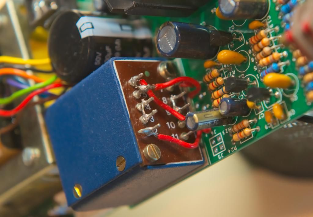
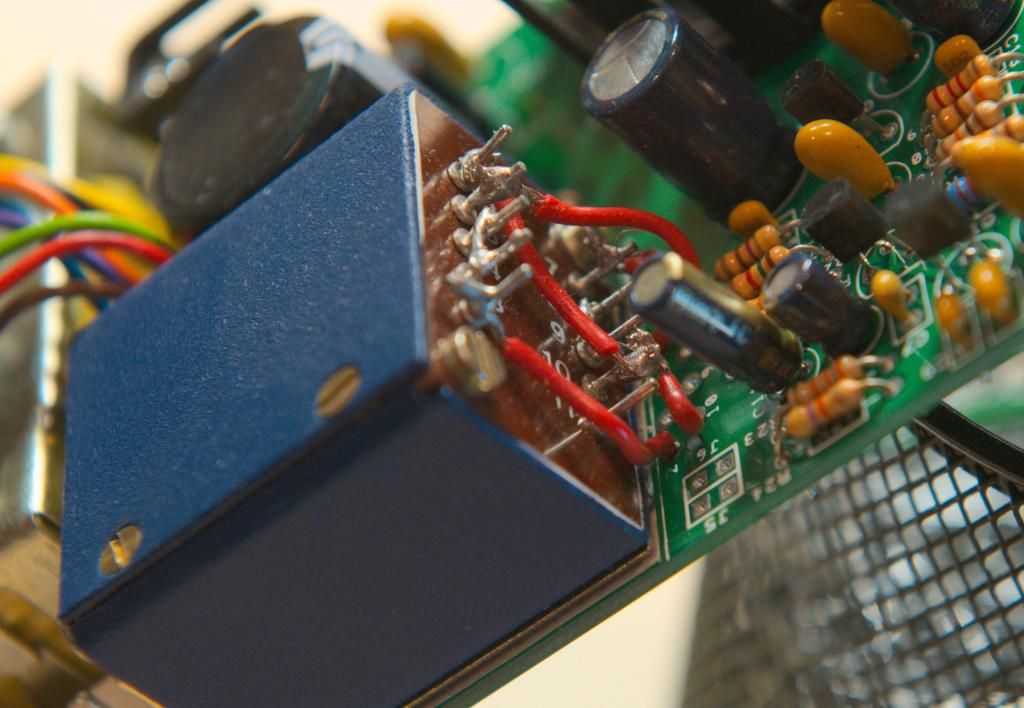
CARD TWO
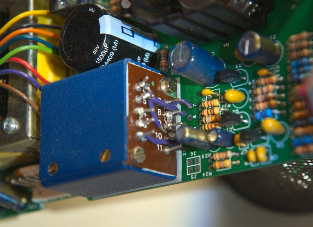
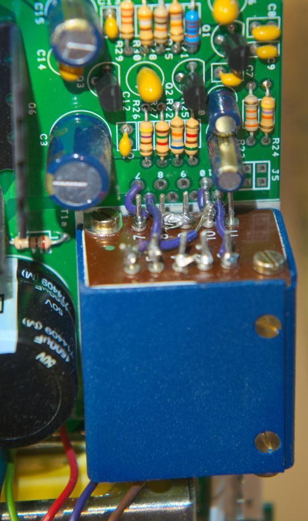
CARD ONE


CARD TWO


Last edited by jdier on Thu Sep 18, 2014 6:10 am, edited 1 time in total.
- jdier
- Posts: 44
- Joined: Mon May 17, 2010 7:43 am
Re: Incorect voltages
![]() by tpryan » Tue Sep 16, 2014 1:29 pm
by tpryan » Tue Sep 16, 2014 1:29 pm
Does noise increase with gain? If so, does the trim control affect the noise level?
- tpryan
- Site Admin
- Posts: 2078
- Joined: Thu Dec 04, 2003 11:32 pm
Re: Incorect voltages
![]() by jdier » Wed Sep 17, 2014 6:14 am
by jdier » Wed Sep 17, 2014 6:14 am
tpryan \$m[1]:Does noise increase with gain? If so, does the trim control affect the noise level?
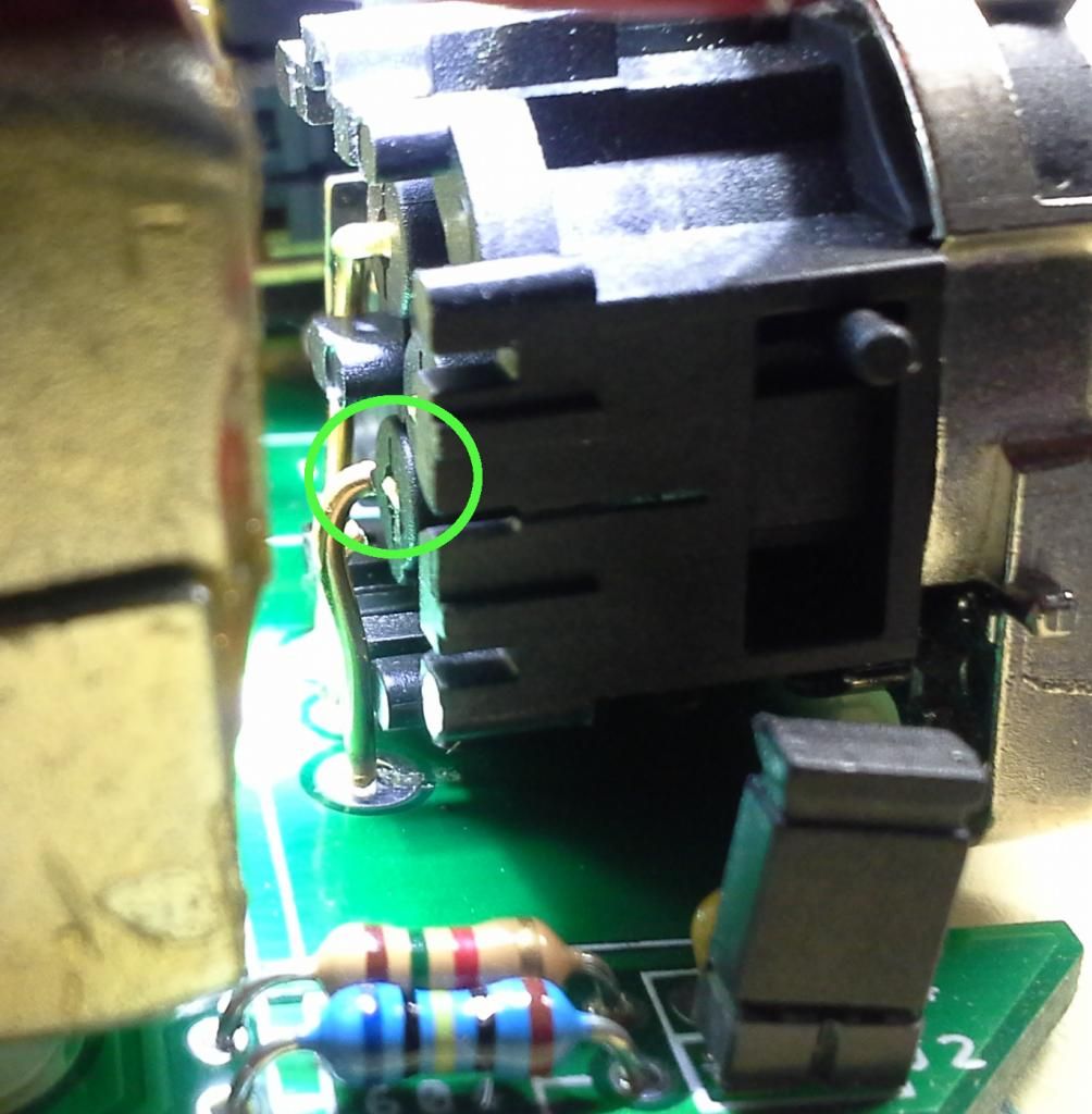
There is a low level buzz on both cards but it does not change with changes to the gain or the trim.
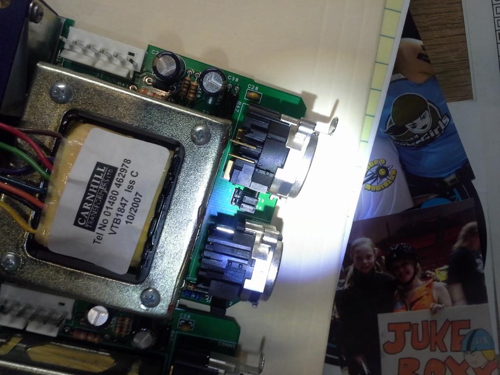
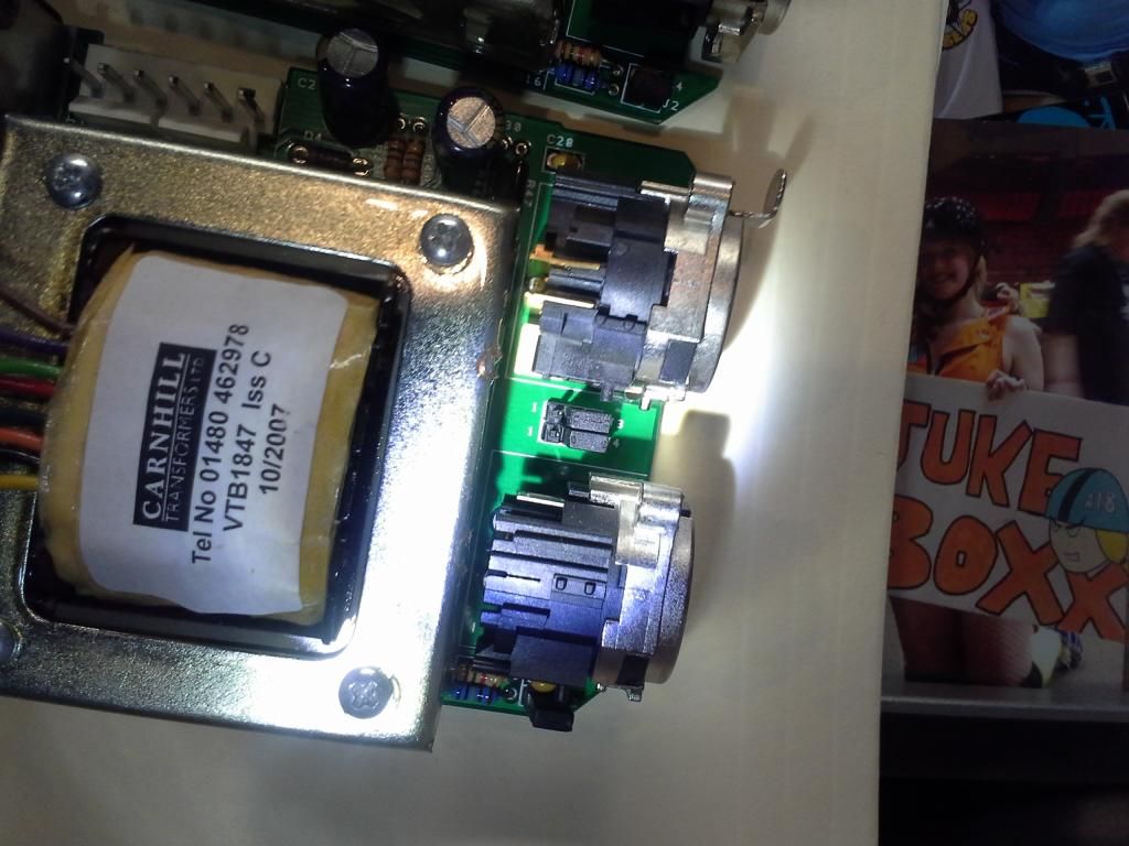
One one of the cards, the output jack may have a broken lead shown circled here:

This card also seems to have a grounding problem in that it buzzes noticably louder when there is not a mic plugged in, and I can also get the buzz to go away by touching the input or output jack.
- jdier
- Posts: 44
- Joined: Mon May 17, 2010 7:43 am
Re: Incorect voltages
![]() by jdier » Wed Sep 17, 2014 6:31 am
by jdier » Wed Sep 17, 2014 6:31 am
Revson \$m[1]:Can you measure continuity between the blue wire coming off T2 and either Pin 2 or 3 on the XLR output? Try doing the same with the violet wire.
No continuity from either blue or purple to any pin on the XLR output.
- jdier
- Posts: 44
- Joined: Mon May 17, 2010 7:43 am
Re: Incorect voltages
![]() by Revson » Wed Sep 17, 2014 7:02 am
by Revson » Wed Sep 17, 2014 7:02 am
The phase reverse switch is the only thing between the output transformer and the XLR connection. If something hit the front panel or it landed funky in shipping, the switch(es) may have been damaged. The two middle pins on the switch should be the inputs and the outside two pairs are the outputs. See if you can get continuity between one of the middle pins and the output pins. Make sure the flip the switch and measure as well.
- Revson
- Posts: 8
- Joined: Sun Feb 03, 2008 9:51 am
Re: Incorect voltages
![]() by jdier » Wed Sep 17, 2014 7:58 am
by jdier » Wed Sep 17, 2014 7:58 am
Continuity testing shows the output jacks on both N72's are shot.
I am thinking this same issue is causing my problems on the A12 that came with these.
I am thinking this same issue is causing my problems on the A12 that came with these.

- jdier
- Posts: 44
- Joined: Mon May 17, 2010 7:43 am
16 posts
• Page 1 of 2 • 1, 2
Who is online
Users browsing this forum: No registered users and 1 guest